Plan Section Elevation Drawings Symbols
Consummate Guide to Blueprint Symbols: Floor Plan Symbols, MEP Symbols, RCP Symbols, and More
Jul 03, 2020

An architectural program, or set of blueprints , is created by architects, engineers, and designers to lay out all the construction specifications of a firm, such as dimensions, building materials, installation methods, techniques, and fifty-fifty the social club in which these things must be achieved.
The number of details that must be included in a complete set of blueprints is then large that architects reduce the information on the drawings to a set of standardized symbols and abbreviations in order to brand the cartoon easier to read and less chaotic.
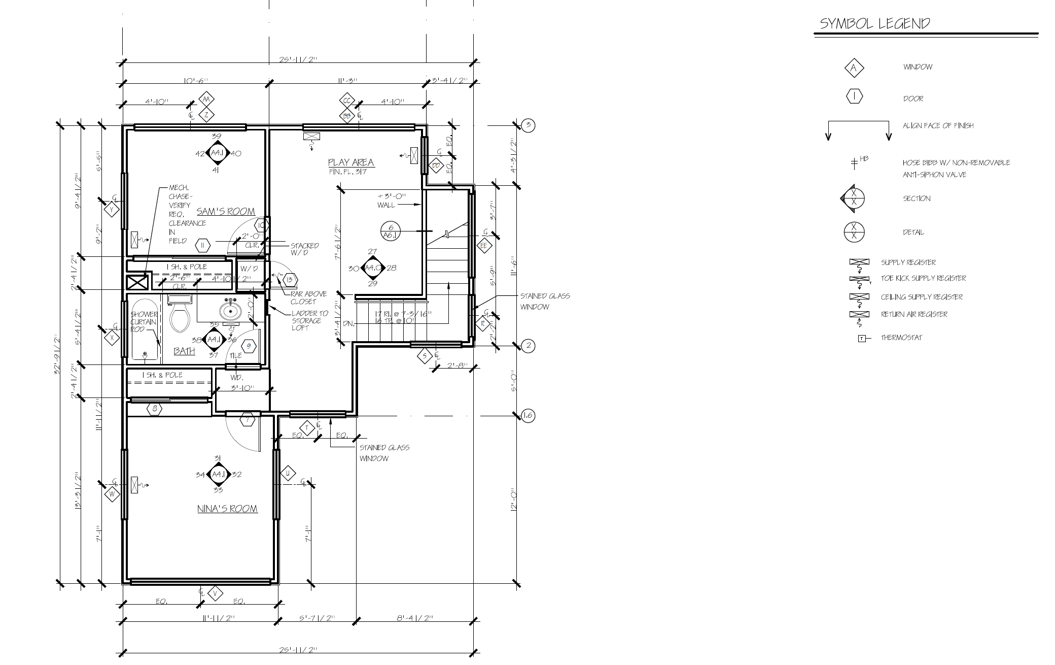
For reference, every set of architectural drawings includes a symbol legend. If you aren't familiar with a symbol, you will be able to find it in the legend. Floor programme notes give boosted context for the building. For instance, the notes tin can clarify exactly to what point on a wall dimensions should be measured.
Most plans include symbols that are a combination of:
- Appearance (for instance, a bathtub looks like a bathtub)
- Conventions (double lines are commonly used to announce walls)
- Labels (for instance, a thermostat is labeled "T").
Architectural symbols and scale
In order to fit all the data about a layer of a edifice onto a page, construction drawings and architectural drawings are drawn so that a small increment of measurement represents a larger increment. This means that the plans are fatigued "to scale." Every symbol on the legend is fatigued to the same scale every bit the rest of the floor plan.
Scales vary in complexity, from the elementary (i inch = 1 foot) to the circuitous (iii/16 inch = i foot). Plans are often drawn at 3/four, iii/sixteen, 1/8, and other scales (in each instance the dimension in inches hither corresponds to 1 human foot). The symbols are also drawn to scale so you volition get an authentic thought of how elements of a room are configured in the space.
The calibration is ever shown on the same page as the drawing, either under the title or below an individual drawing. Keep in mind that scales can vary throughout a set up of architectural prints, and then check each page and use an architectural scale , or scaled ruler, to make sure you're reading the print accurately.
Recognizing symbols is a get-go step towards reading a property'southward blueprints. Larn everything you need to know about reading blueprints in MT Copeland's online class , taught by professional architect and craftsman Jordan Smith.
6 Common types of floor plan symbols
Imagine a view of a habitation sliced horizontally about five feet from the ground and looking down from in a higher place. This is the style a flooring plan is drawn, and it is designed to requite yous a detailed idea of the layout of each flooring of the firm. This is merely one of the components of the consummate set of blueprints.
The types of plan symbols you'll discover on floor plans include everything from doors and stairs to appliances, furniture, and electrical symbols.
Here are the six nigh common types of symbols you will find on flooring plans (versus other types of plans).

1. Compass
The north pointer tells you about the orientation of the property. Builders and architects use "Projection North" as a designation, which is dissimilar from the cardinal directions on a compass. This allows you to navigate through the house by using due north, due south, east, and west without having to know where due (magnetic) north is.
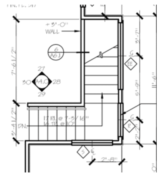
ii. Stairs
Stairs are customarily indicated by parallel lines with their measurements. In this instance, we run across that they are placed between a window (the triple line indicated by a diamond), and an interior architectural wall (the double line).

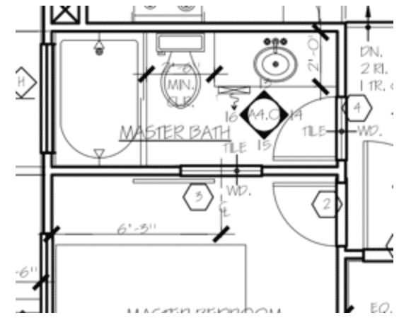
3. Doors
Doors, indicated in this programme with a numbered hexagon symbol, are drawn with a direct line indicating the door itself; the curved line shows which mode the door swings open up, to show architects and designers the amount of clearance they will have in the room.
iv. Windows
A window is commonly denoted with three lines, vs. a wall's ii parallel lines. It is also indicated with a numbered diamond, which shows which window it is on the window schedule. As y'all await at symbols such as the diamond for window, look for important abbreviations that describe it, such as EQ, or "equal." This volition help y'all sympathise the dimensions of what the symbols are describing. For case, a C with an 50 through information technology is a center line, and describes that a window is centered, with equal distance on either side.
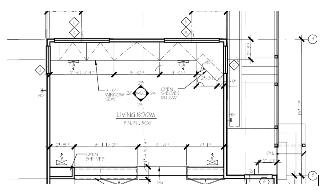
5. Walls
Walls are ordinarily indicated with a unmarried line for interior lines, and are drawn with thick, dark line weights, commonly in double lines, to indicate exterior walls. As you lot can see on this programme, the builder has also given the length for each wall.
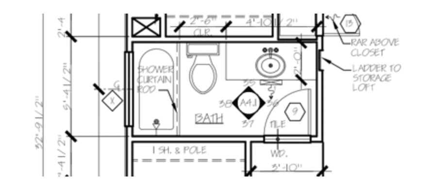
6. Appliances
Appliances and fixtures, such as toilets, sinks, and bathtubs, are drawn to scale with a thin line, and resemble the item they symbolize. Similarly, the furniture in floor plans is drawn with a light line weight so y'all can quickly tell that it is not integral to the edifice. It's placed at that place for reference so that anyone looking at the flooring plan tin sympathise how the rooms were intended to be prepare.
Appliances and fixtures such as cabinets and the microwave are often drawn with a dotted line. The nearly pertinent information, such as walls, doors, and windows, are drawn in heavier weights, so your eyes will be drawn to them immediately.
Symbols found on other prints in an architectural package
Each of the components of the architectural plan volition take its own set of symbols and notes. Architects and designers piece of work with the floor plans, and you'll also see exterior and interior elevations, and reflected ceiling program (RCP) . Here are the virtually common establish on each blazon of print .
MEP (Mechanical, Electric, and Plumbing)
Other types of prints inside the architectural plan include MEP, or Mechanical, Electrical, and Plumbing. They are normally delivered in a parcel on a split drawing with the relevant mechanical, plumbing symbols, and electrical symbols. Every bit a architect or framer, yous'll need to know where those systems will exist routed then y'all tin can leave space for them to be laid in. The MEP drawings volition prove the location of physical fixtures and the routing of the lines.
Plumbing drawings reverberate the complex piping and sewage routes for the building, and these are examples of symbols you lot volition find on the plumbing plans:
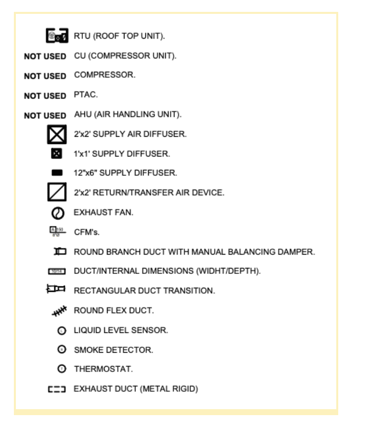
Mechanical drawings reflect the heating, ventilation, and air workout (or HVAC) systems of a building. Hither are some of the symbols you will see on mechanical plans:
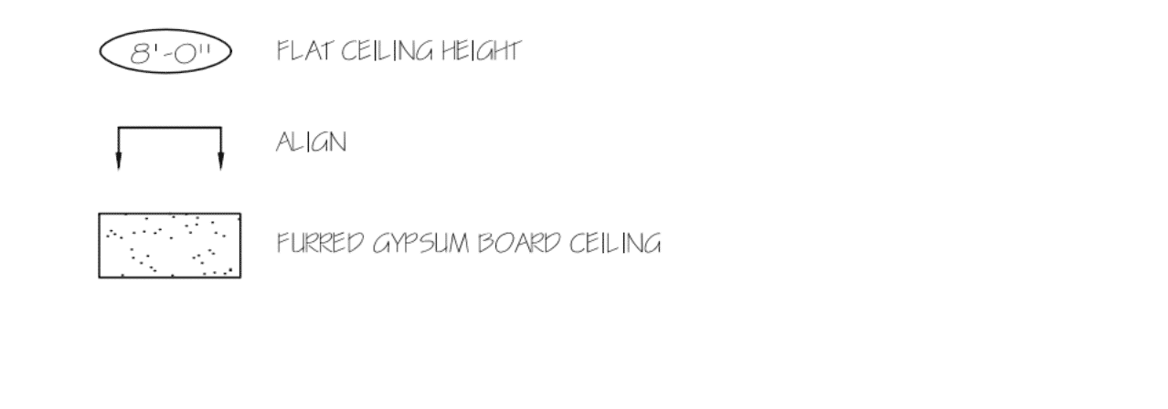
RCP (Reflected Ceiling Plan)
Architects and builders describe reflected ceiling plans (RCP) to show the dimensions, materials, and other key information nearly the ceiling of each of the rooms represented on the blueprint. Information technology takes its proper noun from the idea that yous are looking down at the ceiling equally though there were a mirror on the floor reflecting the ceiling's plan back to you. Hither are common RCP symbols:
MT Copeland offers video-based online classes that give you a foundation in construction fundamentals with existent-world applications. Classes include professionally produced videos taught by practicing craftspeople, and supplementary downloads like quizzes, blueprints, and other materials to help you master the skills.
gillenwaterwenstoced.blogspot.com
Source: https://mtcopeland.com/blog/complete-guide-to-blueprint-symbols-floor-plan-symbols-mep-symbols-rcp-symbols-and-more/
0 Response to "Plan Section Elevation Drawings Symbols"
Post a Comment